What is a Battery Management System (BMS)?

On a ship, a Battery Management System (BMS) is an integrated control and monitoring software which continually ensures the safe operation of a battery propulsion and/or storage system on board.


BMS software has large bandwidth and uses an ethernet connection with remote update capability and protocols to mitigate packet loss.


BMS carry out the following services:


• Ensures smooth and safe system start-up
• Provides current control to ensure the optimal charge/discharge rate for battery longevity
• Alarms and warnings including early identification of potential points of failure, hidden failures and failure prediction
• Remote monitoring and reporting of battery performance to inform maintenance


Redundancy is provided using direct emergency stop controls for the crew, redundant power supplies for each string, Redundant Management Software and remote monitoring for onshore investigation of anomalies by the service team.


– Information from SHIFT Clean Energy –

How is the safety of the crew and ship assured during battery installation?

The safety of crew and installation personnel is of utmost importance. A variety of hardware and integrated software protocols. These systems work together to protect the crew and system during the installation procedure.


 Safety mechanisms – Image courtesy of SHIFT Clean Energy


Safe voltage isolation is provided with:


  • A contactor in every module
  • No voltage during shipping
  • Arc flash prevention during installation
  • No voltage in an emergency for personal safety
  • No hydrogen generation when submersed in sea water
  • Use breaker to isolate string instead of contactor + fuse


During start-up:


  • Motorized breaker connects ESS to the DC Bus
  • BMS checks for correct cabling prior to enabling internal contactors and switching on battery
  • Once setup complete, system waits for control command
  • to connect to the DC Bus
  • Final DC Bus connection performed by motorized breaker
  • Ensures operator/installation safety and system isolation


–  Information from SHIFT Clean Energy –

What is thermal runaway and how is it prevented?

Thermal runaway is a catastrophic overheating of the battery, causing a fire that generates toxic gases and risk of explosion. The fire can propagate between batteries and adjacent materials/structures. In a marine environment, this obviously causes great danger to the crew, the ship and any passengers on board.


Causes


There are a number of different ways thermal runaway can occur, as shown in the diagram below.


Image courtesy of SHIFT Clean Energy


Prevention


Maintaining low cell temperature at high power cycling or in a fault scenario is the key to lithium-ion safety. Keeping the internal temperature of each cell below the thermal runaway threshold ensures prevention.

For specific causes, the prevention measures below will remove the risk of thermal runaway.


Cause


Prevention


Negligent Charging / Discharging Include voltage upper and lower limits using BMS software and hardware sensing of each cell with direct trip line to DC breaker
High external temperatures Encase cell in cooling liquid to prevent heat from reaching the cell.

Ensure cooling water is flowing at all times and prevent external fire from reaching batteries.

External Short Circuit /  High Current Encase cell in cooling liquid to prevent heat from reaching the cell.
Mechanical Damage Crush proof cell casing passing UN38.3 transportation tests.

SPBES PlanB uses 19mm of aluminum armor protecting cell edges.

Dendrite Formation Encase cell in cooling liquid to prevent heat from reaching the cell. If an internal short occurs from dendrite or manufacturing defect – the liquid cooling is able to remove more heat than a runaway cell is able to produce. Required coolant flow between 0.5GPM and 2GPM for RMS C rates between <0.1 and 3C.


The Patented SPBES Thermal Management System is designed to prevent thermal runaway. Through thorough cooling of the cell, we facilitate the ability to use all of the available energy within the cell to its full potential- safely. By taking the heat away from the cell as it is created, we keep the cell temperature at ideal performance range (around 25 °C) and prevent the internal cell temperature from accelerating to the point where thermal runaway occurs.


– Information from SHIFT Clean Energy –

What different types of batteries exist?

Lithium-Nickel-Manganese-Cobalt (NMC):


NMC chemistry provides the greatest balance of power, energy, safety, and overall performance compared to other lithium-ion technologies, including Lithium Titanate.


These batteries are suitable for powering fully-electric or hybrid-electric ships.


Image courtesy of SHIFT Clean Energy


Lithium-Titanate-Oxide (LTO):


Compared to other lithium-ion battery chemistries, LTO batteries tend to have an average power rating and lower energy density. They have an ultra fast charge and discharge capability, extremely long cycle life (>60,000+ cycles at 100% DOD) and are capable of a fast charge in <10 minutes.


Image courtesy of SHIFT Clean Energy


These batteries are suitable for powering Dynamic Positioning, for example on offshore service vessels.


NTK Victoria – Image courtesy of SHIFT Clean Energy


Lithium Iron Phosphate:


Compared to the other lithium-ion technologies, LFP batteries tend to have a high power rating and a relatively low energy density rating.

Comparing types:


Image courtesy of  SHIFT Clean Energy


Information from SHIFT Clean Energy

What happens to batteries at the end of their use life?

To minimise the use of rare and precious metals, batteries should be optimised to allow for durability and recycling at their end of life.


Zero Emissions Services marine ZESPack is guaranteed to last 10 years. After 10 years, the capacity of the batteries is reduced by about 20%. Use of the ZESPack for another 10 years is possible in numerous other applications. At the end of this lifespan, the materials can be recovered and made suitable for reuse. Due to the long service life of the ZESPack, the system saves far more in emissions than it costs to build the batteries. (From Zero Emissions Services)


Image courtesy of Zero Emissions Services


The SPBES PlanB CellSwapTM is a retrofit process to rebuild the inside of a battery onboard a vessel. The cells in the core of the battery can be replaced when nearing the end of their life. If there is a requirement to service the cell stack, then the battery is removed from the ship and sent to the service depot. Since the cells can be replaced individually, only the cells at the end of their life need replacing instead of the entire battery. Other items, such as electronics and racking, are reused. There is no need for costly refit of existing hardware, only the consumable parts such as the cells are replaced.


SPBES offers support from commissioning to recycling, consisting of:


  • Options for re-coring or recycling the system, including time and costs
  • System decommissioning and arrangement for delivery of consumables to accredited recycling facilities included in the cost of the LPA
  • A report of proof of recycling provided


– From SHIFT Clean Energy

What standards and certification exist to ensure battery system safety and quality?

Components and systems used in the maritime industry need to meet high requirements for safety and reliability.


For ships, leading IACS Classification Societies have produced certifications, standards and guidelines for operating with fully electric propulsion, hybrid-electric propulsion and Energy Storage Systems (ESS).


Information from SHIFT Clean Energy

What is the lifetime of batteries?

Cell life is affected by:


  • Charge Rate
  • Maximum voltage
  • Temperature


The cycle life is the number of complete charge/discharge cycles that the battery is able to support, and is used to measure battery lifetime.


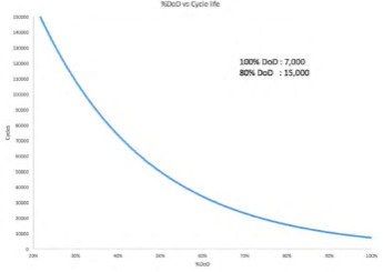
DoD vs Cycle Life – Image courtesy of Sterling PBES Energy Solutions


Charge Rate


The more charge/discharge cycles are completed, the lower the Depth of Discharge (DoD), or percentage of the energy removed from the battery.


Chemistry is a critical influencer of cycle life, and even then the detailed breakdown of the chemistry can alter the basic performance characteristics of the chemistry. Influencers like silicon can improve some aspects of performance in all chemistries, but they can also negatively impact aging, heat generation and degradation. Each chemistry relies on the integrity of its manufacturer and how “fit for purpose” it is for the markets we are applying it to.


Aging increases non-linearly with a higher charge rate (C-rate). So, the higher the C-rate, the fewer cycles the cell can undergo, reducing its lifespan.


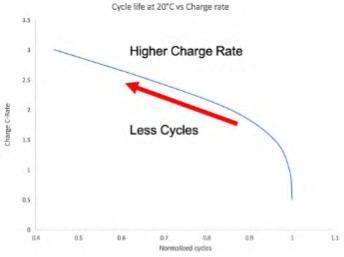
Cycle life vs C rate – Image courtesy of Sterling PBES Energy Solutions


On the other hand, Discharge rates are much less impactful than Charge rates, due to the chemical construction of the cells. On discharge, power is effectively ”allowed” to leave the battery unencumbered. We can discharge at very high rates of power; up to 10x the capacity of the system for short bursts.


But, in marine applications, we need to engineer for continuous power- and this means we limit our discharge with NMC batteries to 5C or 5 times the rated capacity of a system. SPBES can manage this generation of heat without compromising the life of the battery.


Maximum Voltage


Aging increases rapidly with higher cell voltage, even if voltage is reached only momentarily.


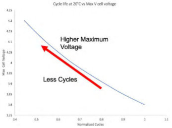
Cycle life vs Voltage – Image courtesy of Sterling PBES Energy Solutions


Temperature


Aging increases rapidly with higher cell temperatures during operation.


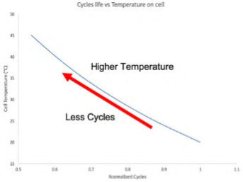
Cycle life vs Temperature – Image courtesy of Sterling PBES Energy Solutions


– Information from Sterling PBES Energy Solutions

How do batteries work?

A battery is a container consisting of one or more cells, in which chemical energy is converted into electricity and used as a source of power.


An SHIFT battery can be configured in capacity from 26kWh to multiple MWh. (From SHIFT Clean Energy Solution)


Image courtesy of  SHIFT Clean Energy


Ions move from positive (cathode) to negative (anode) during charging and reverse during discharging.


Image courtesy SHIFT Clean Energy


The Rated Capacity (C) of a battery is measured in Ampere Hours (Ah). It defines the size of the “gas tank” and is the current a battery can deliver from fully charged to fully discharged for a period of one hour.


The C-Rate is the rate of charge or discharge expressed as a function of the rated capacity. It Defines how fast the “gas tank” can be drained.


The rated capacity at the battery nominal voltage is expressed in Watt hours (Wh).


– Information from SHIFT Clean Energy Solution –