Future insight
Exploring technologies
The application of additional energy efficiency technologies to reduce energy demand is essential in combination with the use of alternative fuels to achieve the net-zero ambition. This section provides information on individual technologies.
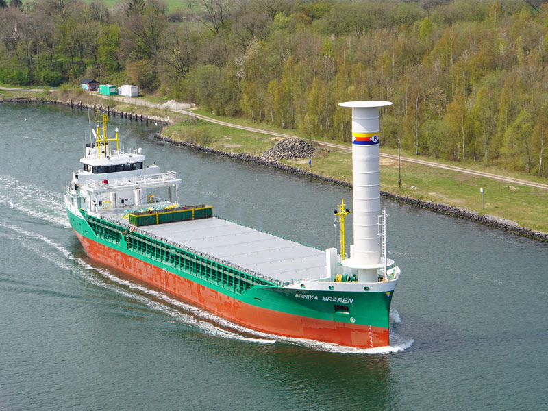
Wind propulsion
Wind propulsion technologies (WPTs) enable the harvesting of an inexhaustible, zero-emissions and zero-cost energy source. The use of renewable wind energy directly for ship propulsion has undergone remarkable modernisation over the last ten years to become a powerful emissions-reducing technology that reduces reliance on costly commoditized fuel. A variety of modern WPTs are available that can be deployed as retrofit wind-assist, optimised new build wind-assist or as a primary wind ship.
Battery
Electrification is the backbone to energy-efficiency and enables quiet propulsion. Currently, hybrid-electric vessels are able to significantly reduce emissions by storing unused energy for high-power operations while fully-electric vessels are limited to specific operational profiles due to the low energy density and charging time requirements. Electrical systems integration allows for input from multiple energy sources such as wind, fuel cells and battery packs, enabling for maximum efficiency.
Fuel cell
Fuel cell technology has been around a long time but has only recently become commercialized in the transport sector for road vehicles and for stationary power generation. Currently, fuel cells are being demonstrated on coastal and inland vessels. In a fuel cell, electricity is produced by the oxidation of hydrogen with the emission of water vapour.
Onboard carbon capture and storage
Onboard carbon capture and storage (OCCS) systems are a potentially important technical solution to the reduction of GHG emissions in shipping as the industry transitions toward low- and zero-carbon fuels. OCCS systems remove and store CO₂ from exhaust for later deposit at appropriate onshore facilities.
ZESTAs AZ De-emission Tool
The AZ De-emission Tool, specifically designed to help ship operators and stakeholders in navigating the process of decarbonizing vessels, provided along with other useful information on the Zero Emissions Ship Technology Association (ZESTAs) website.
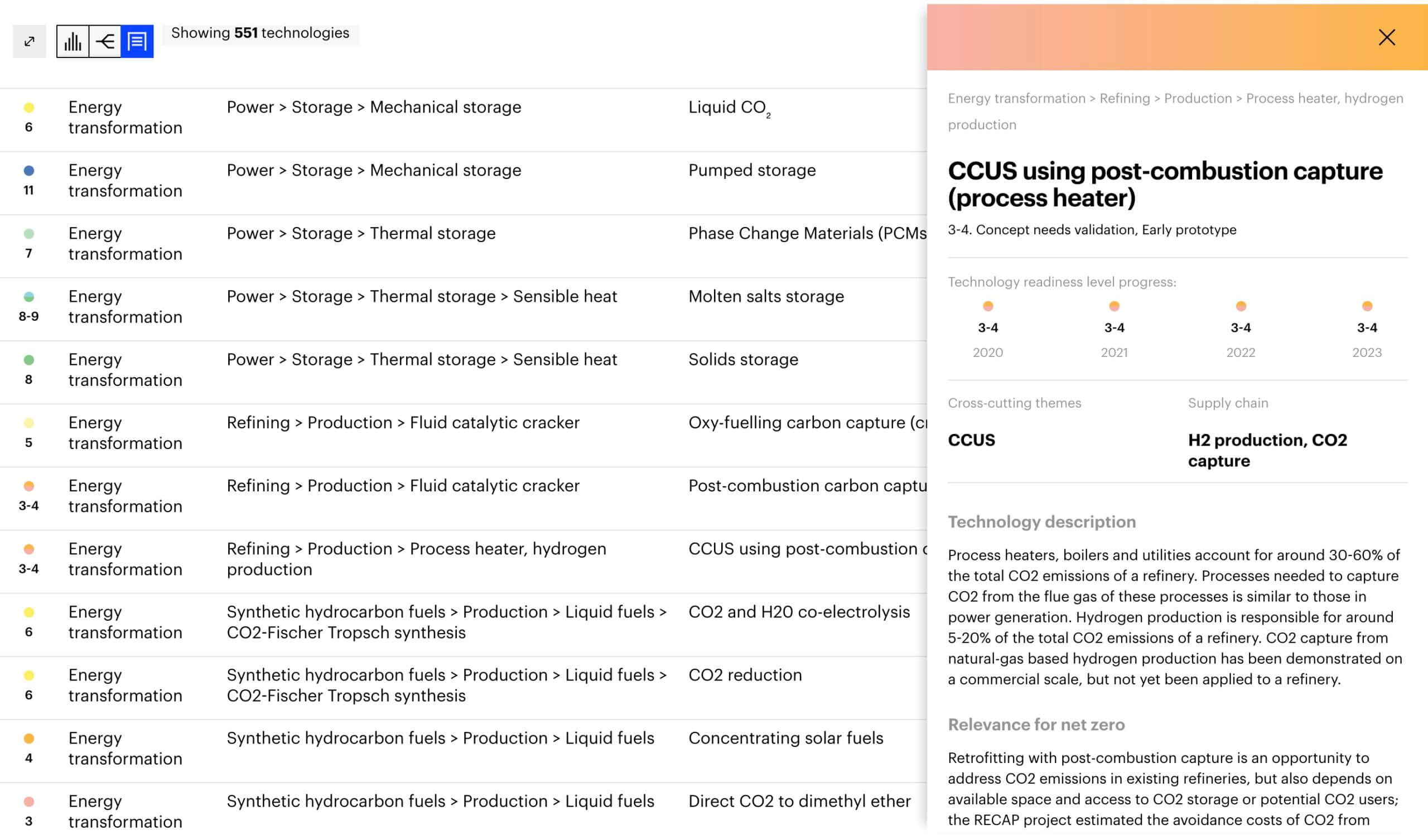
Technological readiness
WTP Clean Energy Technology Guide (IEA) provides information on the level of maturity, a compilation
of development and deployment plans, cost and performance improvement targets, and leading players in the field.